
Network Redesign Part 1: Overview
A new look at my home office

Thursday June 26th 2025
I come to realize that splitting services into different VRFs was not such a good idea after all. Therefore, I have revised my design with only one VRF for the entire datacenter infrastructure.
This part is going to give an overview of the changes I made. Next part will cover some routing configuration, as it was more work to it than I thought.
Design revisions
Layer 3 Design
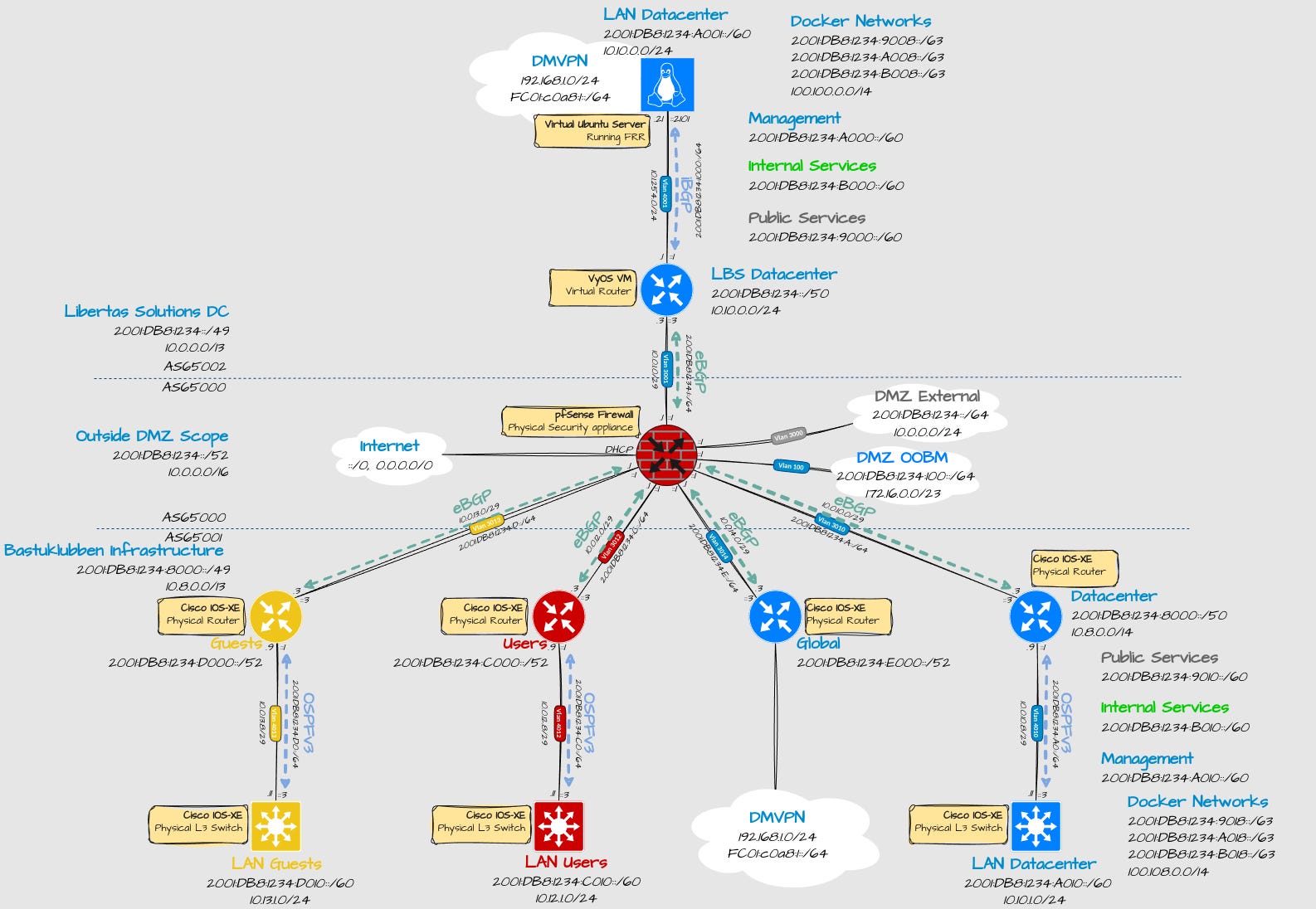
Explanation:
Inside Bastuklubben infrastructure:
At the moment, 3 VRFs are defined:
USER = Internal user network
GUEST = for guest access, duh
NMS = Datacenter infrastructure. I reused the name and IP ranges from the old design.
Global is referring to the global routing table.
A big difference is that instead of having separate VRFs for different types of services, they all share in the same VRF. Restricting access between containers will instead be handled by the firewall on the container management nodes and the internet edge firewall. I achieved this by using multiple IPv6 prefixes on the same LAN interface.
2001:DB8:1234:X010::/63 is reserved for LAN subnets.
2001:DB8:1234:X018::/63, is reserved for container networks.
To make broad isolation rules easy to implement, I still have different categories defined:
2001:DB8:1234:A018::/64 - The default docker networks. For testing.
2001:DB8:1234:9018::/63 - Services that should be reachable from the internet.
2001:DB8:1234:A018::/63 - Network and management services
2001:DB8:1234:B018::/63 - Services only reachable internally.
When using docker, you have to make IPv6 prefixes shorter than 64, as I have explained in Docker Networks Part 1. That is why all IPv6 prefixes will be defined with a /80.
A GRE tunnel is inside the Global Routing table. It connects the two datacenters together. Why it’s in the global routing table and not inside VRF NMS will be explained in part 2.
Inside Libertas Solutions
This is my so called cloud solution. Bastuklubben is one tenant in there.
Only datacenter networks are needed.
2001:DB8:1234:9000::/60, 2001:DB8:1234:A000::/60, 2001:DB8:1234:B000::/60 is advertised to Bastuklubben main site and datacenter uplink router.
Libertas Solutions has it’s own IP prefixes. IPv6 NPT and static NAT44 has been implemented to make internet connectivity work for hosts inside the cloud.
The Ubuntu Server1 is configured as a router but only using the global routing table (except for a OOBM VRF for SSH connection).
Layer 2 Design
There are some significant differences in Layer 2 as well, at least on the cloud infrastructure side:
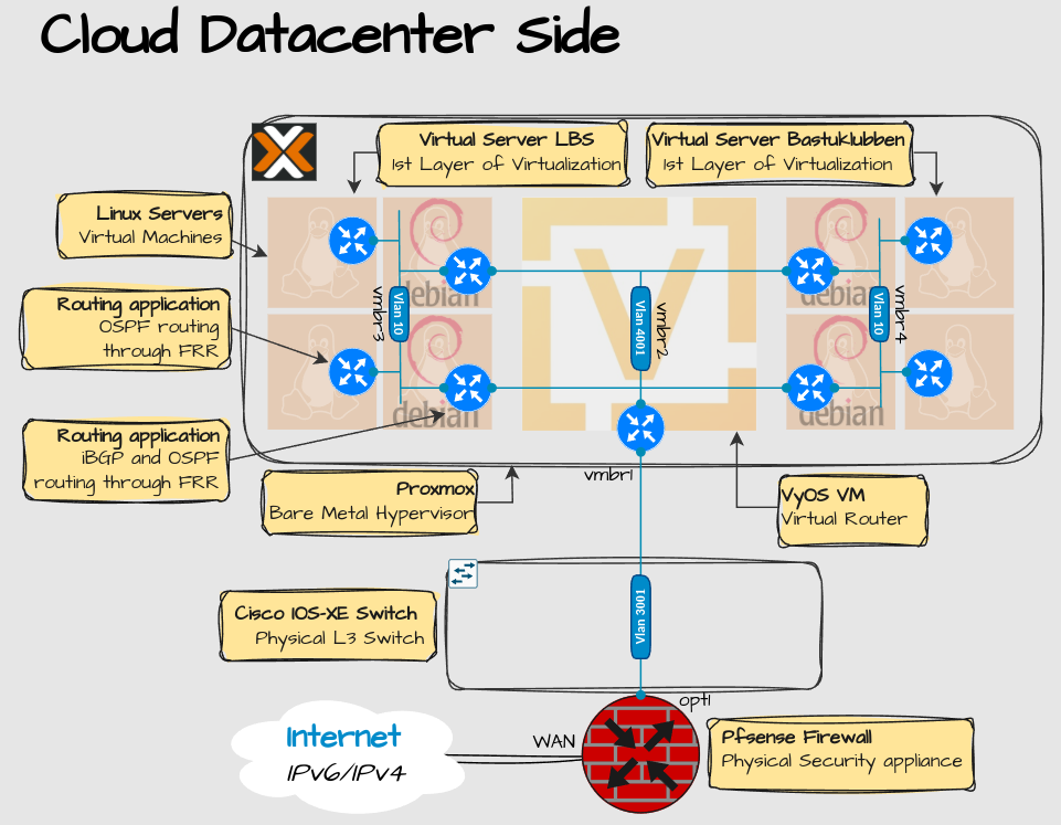
Explanation:
Only one linknet VLAN for all tenants is needed. Filtering traffic between tenants is taken care of by the Proxmox Firewall.
Every tenant can have two Linux Debian servers, acting as routers, to terminate on VLAN 4001. Debian works best for advanced routing.
Behind the two Debian servers can be any type and amount of Linux servers, as long as they can install FRR and enable OSPF routing. They terminate on VLAN 10.
To be continued
So how did I manage to implement this? See Part 2 about how this was all configured.
Not shown in the picture but there is actually more than one server in the cloud. I didn’t want to include that because there would be to many details. That will be covered in part 2.