
TrueNAS Network and Storage
How-To: TrueNAS Setup Part 2

17th April, 2023
Updated 2nd August 2025
Updated again 3rd August 2025
Updated 5th August 2025
Update: TrueNAS has evolved rapidly since I last installed it. TrueNAS Core is deprecated and TrueNAS Scale is the new community edition. It is no longer based on FreeBSD but on Linux as the core OS. Therefore, I have updated all the instructions.
Update 2: The more I learn the more I understand. My Initial plan was to use two different datasets to use with applications but I found out that using L2ARC and SLOG caching is a simpler way of increasing performance and stability of apps.

Update 3: WARNING This project turned out to be COMPLETELY USELES for TrueNAS. It’s not possible to use an iSCSI network drive for Apps or anything because the UI won’t recognize it. But if you want to know how to manually configure iSCSI and ZFS on Linux, then there is some value in here.
In this guide I’m going to configure Network Interfaces and Storage Pools that are going to be intended for future applications.
Network Design
Physical Network Design

Explanations:
The MTU on the storage network will be set to 9000.
The network interfaces on the Supermicro server are assigned in this way:
eno1 is dedicated for MGMT of TrueNAS, and is untagged.
eno2 is a tagged port dedicated for VMs and containers (not shown here)
eno3 and eno4 are bonded into lagg1 for iSCSI storage network
The bonded interfaces could be a point-to-point link between the Synology and the Supermicro server. However, this setup gives some scalability options:
The ports are tagged with VLAN 8. This means I can assign another VLAN for another iSCSI link later, or any other type of storage network, and use the same physical ports.
The ports connect to a switch, making it possible for other systems to also connect to the iSCSI target.
A consideration of this is that an attacker could potentially exploit this if the VLAN is leaking out on other ports. Make sure the VLAN is only available on appropriate ports.
The switch can be any managed switch that supports VLANs and LACP (802.3ad).
Note: TrueNAS highly discourage iSCSI network drives for ZFS and is therefore hidden from the webGUI. I’m aware that my setup is not ideal but I have no choice as I’m stuck with the hardware that I got.
However, I’m going to do as much as I can to minimize the load on the iSCSI disks by setting up appropriate caching solutions. My biggest concern is not slow performance, but the risk of data corruption.
Logical Network Design
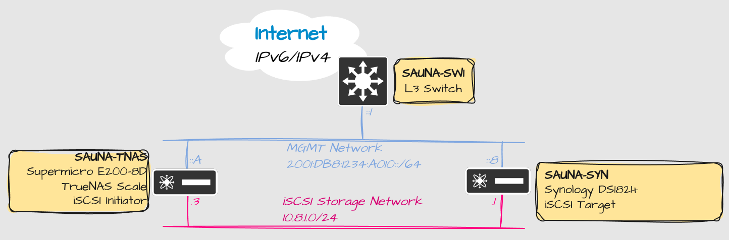
Explanation:
The MGMT Network (VLAN 10) will be IPv6-Only but the Storage Network (VLAN 8) will be IPv4-Only. It’s because of a bug that I experienced when setting up iSCSI network between Proxmox and Synology NAS.
The Multilayer switch is the default gateway for VLAN 10.
VLAN 8 is an isolated network with no external routes.
MGMT Interface Configuration
MGMT Interface configuration was already covered in the TrueNAS installation post.
iSCSI Storage Network Configuration
Let us first cover all configuration necessary for the iSCSI link to work, before configuring TrueNAS.
Switch Configuration
Only configuration relevant to the setup is explained.
Setup MTU, VLAN, tagged ports and Link Aggregation on a Cisco Switch
Configuration
Setting the MTU to atleast 9000 is recommended for storage networks.
Cisco CLI for the win:
! MTU COnfiguration !
!
system mtu 9198
!
! VLAN Configuration !
!
vlan 8
 name iSCSI
!
! Interface Configuration !
!
interface Port-channel1
 description SAUNA-TNAS lagg1 (iSCSI Initiator)
 switchport trunk allowed vlan 8
 switchport mode trunk
 spanning-tree portfast disable
!
interface GigabitEthernet1/0/3
 description SAUNA-TNAS eno3 (iSCSI Initiator)
 switchport trunk allowed vlan 8
 switchport mode trunk
 channel-group 1 mode active
 spanning-tree portfast disable
!
interface GigabitEthernet1/0/4
 description SAUNA-TNAS eno4 (iSCSI Initiator)
 switchport trunk allowed vlan 8
 switchport mode trunk
 channel-group 1 mode active
 spanning-tree portfast disable
!
!
interface Port-channel2
 description SAUNA-SYN bond1 (iSCSI Target)
 switchport trunk allowed vlan 8
 switchport mode trunk
 spanning-tree portfast disable
!
interface GigabitEthernet1/0/5
 description SAUNA-SYN Eth2 (iSCSI Target)
 switchport trunk allowed vlan 8
 switchport mode trunk
 channel-group 2 mode active
!
interface GigabitEthernet1/0/6
 description SAUNA-SYN Eth3 (iSCSI Target)
 switchport trunk allowed vlan 8
 switchport mode trunk
 channel-group 2 mode active
Verification
SAUNA-SW1#show interface description | i Status|iSCSI
Interface                      Status         Protocol Description
Gi1/0/3                        up             up       SAUNA-NAS eno3
Gi1/0/4                        up             up       SAUNA-NAS eno4
Gi1/0/5                        up             up       SAUNA-SYN Eth2
Gi1/0/6                        up             up       SAUNA-SYN Eth3
Po1                            up             up       SAUNA-NAS lagg1
Po2                            up             up       SAUNA-SYN bond1

SAUNA-SW1#show interface status | i Status|iS|lagg|bond
Port         Name               Status       Vlan       Duplex  Speed Type
Gi1/0/3      SAUNA-NAS eno3 (iS connected    trunk      a-full a-1000
Gi1/0/4      SAUNA-NAS eno4 (iS connected    trunk      a-full a-1000
Gi1/0/5      SAUNA-SYN Eth2 (iS connected    trunk      a-full a-1000
Gi1/0/6      SAUNA-SYN Eth3 (iS connected    trunk      a-full a-1000
Po1          SAUNA-NAS lagg1 (i connected    trunk      a-full a-1000 N/A
Po2          SAUNA-SYN bond1 (i connected    trunk      a-full a-1000 N/A


SAUNA-SW1#show etherchannel summary
Flags:  D - down        P - bundled in port-channel
        I - stand-alone s - suspended
        H - Hot-standby (LACP only)
        R - Layer3      S - Layer2
        U - in use      f - failed to allocate aggregator

        M - not in use, minimum links not met
        u - unsuitable for bundling
        w - waiting to be aggregated
        d - default port

        A - formed by Auto LAG


Number of channel-groups in use: 2
Number of aggregators:           2

Group  Port-channel  Protocol    Ports
------+-------------+-----------+-----------------------------------------------
1      Po1(SU)         LACP        Gi1/0/3(P)      Gi1/0/4(P)
2      Po2(SU)         LACP        Gi1/0/5(P)      Gi1/0/6(P)


SAUNA-SW1#show vlan id 8

VLAN Name                             Status    Ports
---- -------------------------------- --------- -------------------------------
8    iSCSI                            active    Po1, Po2

SAUNA-SW1#show interface port-channel 1
Port-channel1 is up, line protocol is up (connected)
  Hardware is EtherChannel, address is 7018.a7a6.a283 (bia 7018.a7a6.a283)
  Description: SAUNA-NAS lagg1 (iSCSI Initiator)
  MTU 9198 bytes, BW 2000000 Kbit/sec, DLY 10 usec,
     reliability 255/255, txload 1/255, rxload 1/255
  Encapsulation ARPA, loopback not set
  Keepalive set (10 sec)
  Full-duplex, 1000Mb/s, link type is auto, media type is N/A
  input flow-control is on, output flow-control is unsupported
  Members in this channel: Gi1/0/3 Gi1/0/4


 SAUNA-SW1#show interface port-channel 2
Port-channel2 is up, line protocol is up (connected)
  Hardware is EtherChannel, address is 7018.a7a6.a285 (bia 7018.a7a6.a285)
  Description: SAUNA-SYN bond1 (iSCSI Target)
  MTU 9198 bytes, BW 2000000 Kbit/sec, DLY 10 usec,
     reliability 255/255, txload 1/255, rxload 1/255
  Encapsulation ARPA, loopback not set
  Keepalive set (10 sec)
  Full-duplex, 1000Mb/s, link type is auto, media type is N/A
  input flow-control is on, output flow-control is unsupported
  Members in this channel: Gi1/0/5 Gi1/0/6
Note: Setting the MTU to more than 9000 globally won’t affect anything negatively.
iSCSI Target Configuration (Synology NAS)
For this we have a Synology NAS Storage Array.
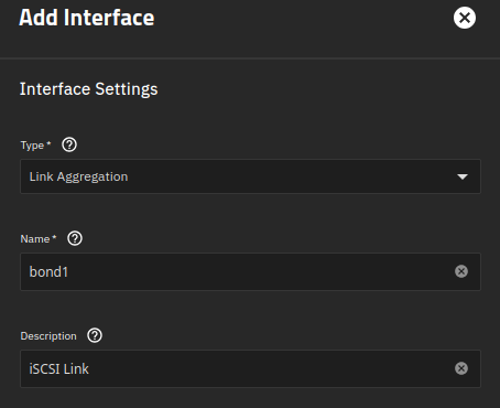
Create a bond interface
Step 1: Go the the Control Panel > Network > Network Interfaces > Create > Bond

Select IEEE 802.3ad Dynamic Link Aggregation as Link Aggregation Mode.
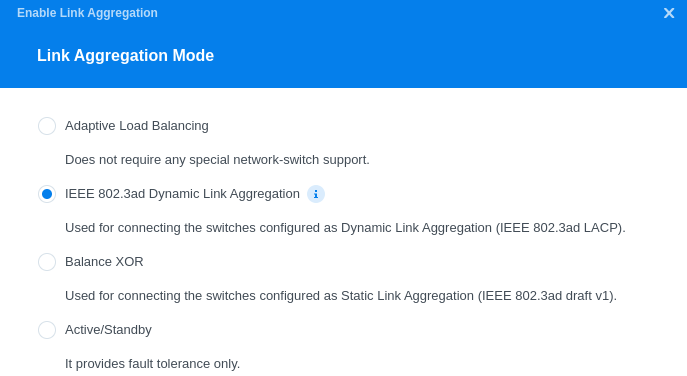
Choose the designated ports and configure the IP parameters.
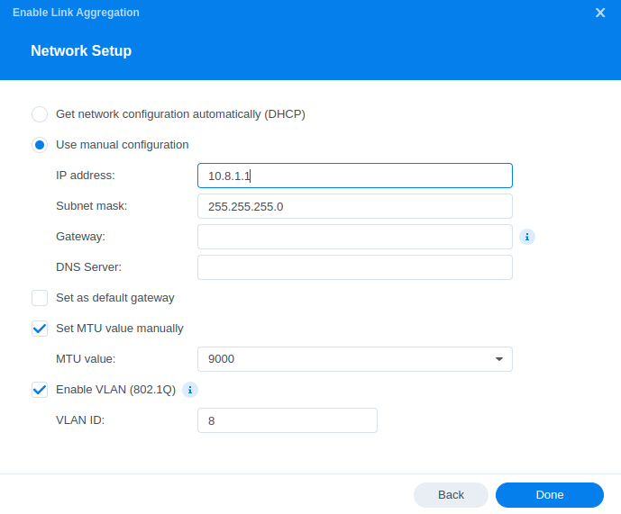
Notes:
No need for DNS or Default GW since this is a closed network segment.
Make sure you configure MTU and VLAN tagging correctly
Configure a Volume dedicated for iSCSI
You need to create a Storage Pool and Volume dedicated for iSCSI. If not done already, go over to Storage Manager > Storage and create a Storage Pool and a Volume.
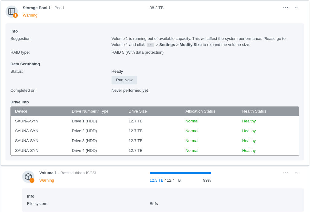
Notes:
The warning is because the iSCSI configuration uses all available storage on Volume 1.
Btrfs is the recommended filesystem for iSCSI and other fileshare configuration.
Configure iSCSI Parameters
Step 1: Go to SAN Manager > iSCSI > Create
The IQN name is automatically generated. There is no need to change it.
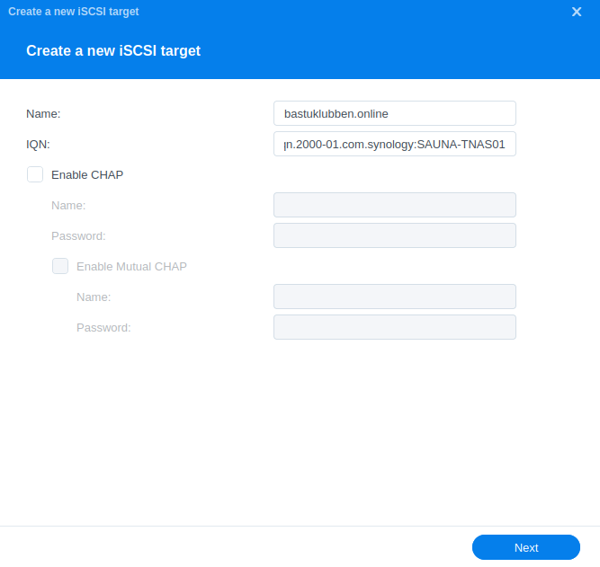
Note: No CHAP Authentication will be used.
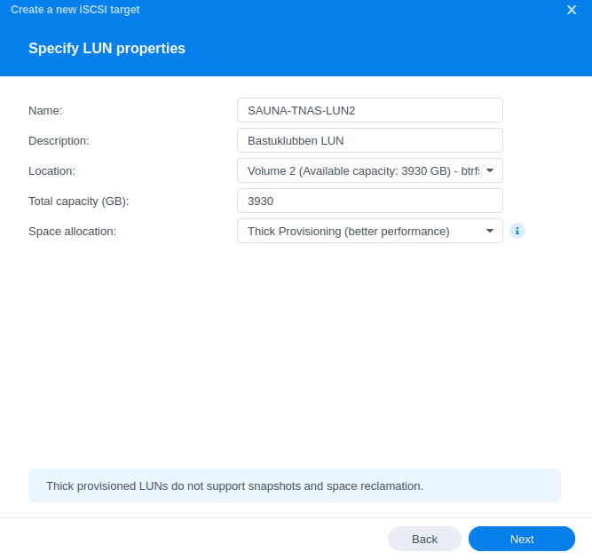
Step 2: On the next page you get to choose LUN. The LUN is where the data should be stored locally on the target. Choose Create a new LUN and choose the Volume created in the last task.
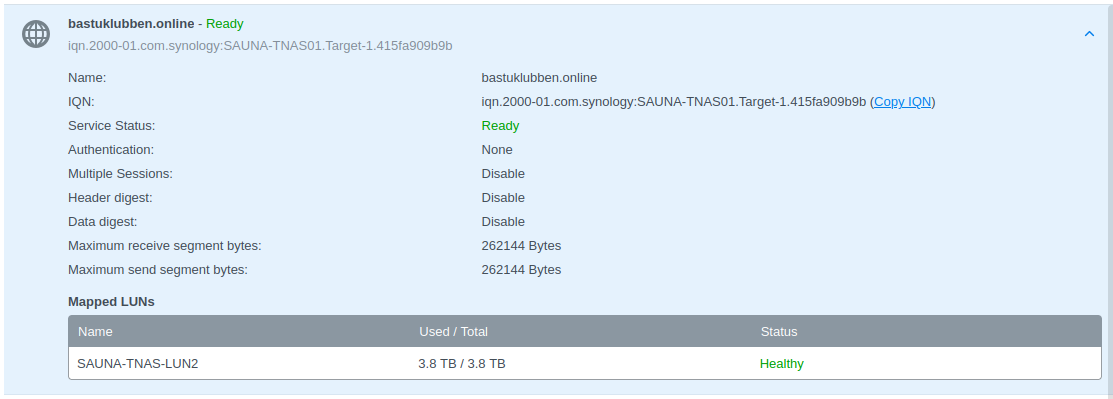
Verification:

iSCSI Initiator Configuration (TrueNAS)
We are now at the point where we can begin to configure TrueNAS for iSCSI.
Create a bonded interface and make it a tagged port
Step 1: Go to Network > Interfaces. Click Add.
Name has to be “bond” followed by a number
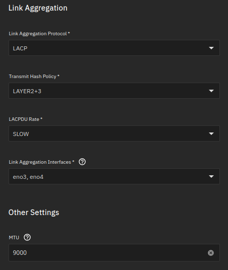
MTU will be set to 9000.
eno3 and eno4 will be assigned to the bond interface.
Link aggregation protocol will be LACP.
Note: No IP address is defined on the bond interface. It will be assigned on the VLAN interface.
Step 2: Create a VLAN interface and assign it to the bond interface.
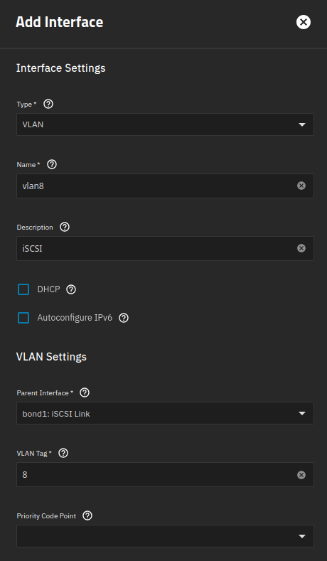
Name has to be “vlan” followed by a number. You could confuse yourself by writing another number than the Vlan Tag, but I won’t.
Parent Interface: bond1
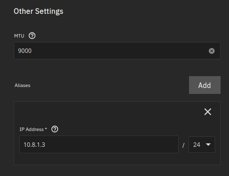
MTU is set to 9000
“Aliases” are IP addresses
Configure TrueNAS as an iSCSI Initiator
UPDATE: Just so you know, this iSCSI drive can’t be utilized for anything useful because TrueNAS WebUI won’t let you use it. I’m considering buying a pair of NVMe drives instead. Therefore, consider this information as general iSCSI and ZFS Linux configuration.
TrueNAS doesn’t support iSCSI Initiation (It is designed primarily for iSCSI Target configuration). However, the underlying operating system is Debian and iSCSI Initiator service is present, although inactive:
truenas_admin@SAUNA-TNAS01[~]$ sudo systemctl status iscsid
○ iscsid.service - iSCSI initiator daemon (iscsid)
     Loaded: loaded (/lib/systemd/system/iscsid.service; disabled; preset: enabled)
     Active: inactive (dead)
TriggeredBy: ● iscsid.socket
       Docs: man:iscsid(8)
We just need to configure the iSCSI initiator from shell.
Note: A big disappointment is that it seems to be impossible to view iSCSI drive from the GUI when configured through shell, something that was possible in older versions of TrueNAS.
Source: https://www.server-world.info/en/note?os=Debian_12&p=iscsi&f=3
Step 1: Open Shell, either via SSH or directly in the GUI. Edit this file:
$ sudo nano /etc/iscsi/initiatorname.iscsiEdit the iSCSI IQD to be the same as configured on the iSCSI Target:
...
InitiatorName=iqn.2000-01.com.synology:SAUNA-TNAS01.Target-1.415fa909b9b
Step 2: Start and enable the iSCSI Initiator service:
sudo systemctl start iscsid
sudo systemctl enable iscsid
Step 3: Run iSCSI Discovery:
$ sudo iscsiadm -m discovery -t sendtargets -p 10.8.1.1Step 4: login to the iSCSI target
$ sudo iscsiadm -m node --login -p 10.8.1.1Step 5: Verify connectivity
$ sudo iscsiadm -m session -o show
tcp: [1] 10.8.1.1:3260,1 iqn.2000-01.com.synology:SAUNA-TNAS01.Target-1.415fa909b9b (non-flash)
Step 6: Enable Automatic Startup:
$ sudo iscsiadm -m node -p 10.8.1.1 -o update -n node.startup -v automatic Step 7: Verify new disk:
truenas_admin@SAUNA-TNAS01[~]$ lsblk -l
NAME MAJ:MIN RM   SIZE RO TYPE MOUNTPOINTS
sda    8:0    0 931.5G  0 disk
sda1   8:1    0 929.5G  0 part
sdb    8:16   0 465.8G  0 disk
sdb1   8:17   0     1M  0 part
sdb2   8:18   0   512M  0 part
sdb3   8:19   0 465.3G  0 part
sdc    8:32   0   3.8T  0 disk
# "sdc" is the new disk
Step 7: Format the disk with parted utility:
$ sudo parted --script /dev/sdc "mklabel gpt"
$ sudo parted --script /dev/sdc "mkpart primary 0% 100%"

$ lsblk -l
NAME MAJ:MIN RM   SIZE RO TYPE MOUNTPOINTS
sda    8:0    0 465.8G  0 disk
sda1   8:1    0     1M  0 part
sda2   8:2    0   512M  0 part
sda3   8:3    0 465.3G  0 part
sdb    8:16   0 931.5G  0 disk
sdb1   8:17   0 929.5G  0 part
sdc    8:32   0   3.8T  0 disk
sdc1   8:33   0   3.8T  0 part
Storage Pools and Datasets
Now when the iSCSI part is taken care of, it’s time to configure a zpool. Unfortunately it is not possible through GUI with a iSCSI drive so everything has to be done through CLI:
Step 1: Create a zpool and mountpoint:
$ sudo zpool create -f container-data /dev/disk/by-id/scsi-3600140540383cfed4844d45eddbde0d7-part1
$ sudo zfs set mountpoint=/mnt/container-data container-data
Note: to create a pool with encryption, read the Appendix
Note: If you get the following error:
$ sudo zpool create -f container-data /dev/disk/by-id/scsi-3600140540383cfed4844d45eddbde0d7-part1
cannot mount '/container-data': failed to create mountpoint: Read-only file system
It means the root partition is in read-only mode, as can be verified with the following command:
$ sudo mount | grep " / "
boot-pool/ROOT/25.04.1 on / type zfs (ro,nodev,relatime,xattr,noacl,casesensitive)
Notice the “ro” in the output. You can change it to “rw” with the following command:
sudo mount -o remount,rw /Then destroy the pool and recreate it:
sudo zpool destroy container-data
sudo zpool create -f container-data /dev/disk/by-id/scsi-3600140540383cfed4844d45eddbde0d7-part1
Step 2: enable LZ4 compression and turn off atime (to mirror defaults on datasets created through GUI):
sudo zfs set compression=lz4 container-data
sudo zfs set atime=off container-data
Update: Read and Write caching
Read Caching
The best way to increase read speeds is to use more RAM for ZFS Cache. The ZFS Cache (also known as ARC = Adaptive Replacement Cache) is used for storing files that are accessed often in RAM. The RAM utilization dynamically scales to cover services and ZFS Cache. If not enough RAM is available for ZFS Caching, it will start reading directly from the disks.
The 2nd best way to increase read performance is to add an Layer 2 ARC VDEV (Virtual Device). For L2ARC to become useful, you have to have such a big demand for reading that the RAM is not enough.
There is some discussion on how useful L2ARC really is. If your NAS already runs with SSD drives, you probably don’t need it. However, it can be very useful if you are using HDD drives (or in my case, HDD over the network). But I would only create L2ARC VDEVs on NVMe drives.
This is the command to add a cache drive for L2ARC caching. It might help reducing the risk of data corruption and will increase read speeds at the same time:
sudo zpool add container-data cache /dev/disk/by-id/ata-CT500MX500SSD4_2009E2900622-part2Note: You don’t need to have a redunant pair of L2ARC drives. It only reads from what is already stored on your dataset. In fact, you can increase performance by adding additional NVMe drives to the caching VDEV.
Write Caching
To understand what write caching does, you need to have an idea of how data is being written to the disk in TrueNAS.
In the dataset settings there are three Syncing modes:
Always = Always synchronize data (synchronous)
Standard = A mix of synchronous and asynchronous data transfer
Disabled = Asynchronous data transfer
To enable zfs synchronization:
sudo zfs set sync=always container-dataSynchronous data transfer means that data is sent to RAM and to a special part of the data VDEV called the ZIL = ZFS Intent Log. Data has to be committed to the disk before the next write operation takes place
To Increase write speed, you can run asynchronous data transfer and it will skip the verification process. Basically the RAM is lying to the system that it has written the data onto the disk already. However that is risky, extremely risky in my case since I have a network drive that can get disconnected.
To disable zfs synchronization:
sudo zfs set sync=disabled container-data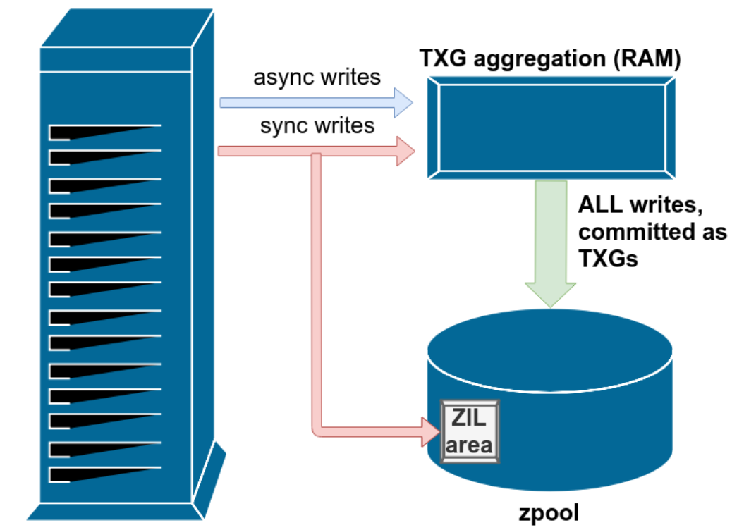
The Recommended approach to increase write speed is to add a SLOG VDEV. This offloads the verification process to a small disk or partition on (most ideally) a pair of SSD drives. NVMe is the best but SATA drives will do as well.
You don’t need much space. 20GB is more than enough if you have a dual 10GB/s link to the network.
Source: Lawrence Systems
To Add an SLOG VDEV to your pool in CLI:
sudo zpool add container-data log /dev/disk/by-id/ata-CT500MX500SSD4_2009E2900622-part1Note: Check the appendix in the bottom if you get an error.
Verification
The disk won’t be visible in the WebGUI but can be verified with following commands:
$ lsblk -fl
NAME FSTYPE     FSVER LABEL          UUID
sda
sda1
sda2 vfat       FAT32 EFI            607C-9A65
sda3 zfs_member 5000  boot-pool      10800737855755617464
sdb  zfs_member 5000
sdc
sdc1 zfs_member 5000  container-data 12953285531044787786
Verification of zpool information can be done with following commands:
$ sudo zpool status container-data
pool: container-data
state: ONLINE
config:
NAME STATE READ WRITE CKSUM
container-data ONLINE 0
scsi-3600140540383cfed4844d45eddbde0d7-part1 ONLINE 0
logs
sda1 ONLINE 0
cache
sda2 ONLINE 0
errors: No known data errors
$ sudo zfs list container-data
NAME USED AVAIL REFER MOUNTPOINT
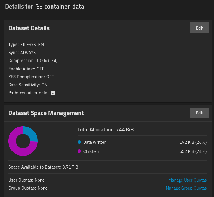
container-data 138K 3.71T 24K /mnt/container-data
$ sudo zfs get atime container-data
NAME PROPERTY VALUE SOURCE
container-data atime off local
$ sudo zfs get compression container-data
NAME PROPERTY VALUE SOURCE
container-data compression lz4 localThe dataset can be verified from GUI, but any changes there may result in python errors. Navigate to Storage > Datasets:
Make the iSCSI disk load at boot
The iSCSI zpool will fail to load during a reboot and has to manually be added with the sudo zpool import poolname command. There is a way to fix that:
Step 1: Enable these system services to scan for zpool storage devices during boot:
sudo systemctl enable zfs-import-cache.service
sudo systemctl enable zfs-mount.service
Step 2: add the zpool to the zfs cachefile
$ sudo zpool set cachefile=/etc/zfs/zpool.cache container-dataStep 3: Edit the zfs-import-cache.service to start after the open-iscsi.service
$ sudo systemctl edit zfs-import-cache.service

### Editing /etc/systemd/system/zfs-import-cache.service.d/override.conf
### Anything between here and the comment below will become the new contents of the file

[Unit]
After=open-iscsi.service
Wants=open-iscsi.service

### Lines below this comment will be discarded

$ sudo systemctl daemon-reload
Step 7: Reboot the system to check if the storage device is stable.
Note: Bootup time significantly increased because it loads the iSCSI disk from the network

Appendix
Create a zfs pool with encryption
If you want to create a pool with encryption, mirroring the same settings as you would get from the GUI, follow these steps:
Step 1: Create a keyfile and store it somewhere in the system. You can delete it later:
sudo dd if=/dev/urandom of=/var/local/container-data_keyfile bs=32 count=1Step 2: Create the Pool
sudo zpool create -O encryption=aes-256-gcm -O keyformat=raw -O keylocation=file:///var/local/container-data_keyfile container-data /dev/disk/by-id/scsi-3600140540383cfed4844d45eddbde0d7-part1Step 3: Generate a key and export it from TrueNAS GUI
Navigate to Datasets > poolname. Scroll down to ZFS Encryption and click Edit
Check Generate Key and Confirm
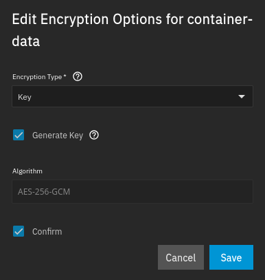
Now you can export the key. You will need that to decrypt the storage in the future.
Issue while adding SLOG VDEV
I kept getting this error when trying to add the slog vdev in CLI:
$ sudo zpool add container-data log /dev/sda1
cannot add to 'container-data': adding devices with different physical sector sizes is not allowed
You can workaround it by creating the vdevs by adding -o ashift=12 to the zpool creation:
$ sudo zpool destroy container-data
truenas_admin@sauna-tnas01[~]$ sudo zpool create \
-O encryption=aes-256-gcm -O keyformat=raw -O \
keylocation=file:///var/local/container-data_keyfile container-data \
/dev/disk/by-id/scsi-3600140540383cfed4844d45eddbde0d7-part1 \
-o ashift=12

$ sudo zpool add container-data log -o ashift=12 /dev/disk/by-id/ata-CT500MX500SSD4_2009E2900622-part1
Related Posts
TrueNAS: Open Source Storage and Hypervisor Alternative
TrueNAS Setup Part 1: Installation of TrueNAS on Bare Metal
TrueNAS Setup Part 3: Virtual Machines and Networks
TrueNAS Setup Part 4: Configuring LDAP and Certificates